Skip to the content
  • Search
    • Deutsch
    • Leichte Sprache
    • Čeština
  • Font/Contrast
    • Change contrast
    • Enlarge font
  • Exhibition
    • The Exhibits
    • Mobile Adventure Land
    • MathsLive
  • Visit
    • Visitor information
    • Contact
  • Adventureland Online
    • Advanced Texts
    • Workshops2Go
    • #enjoyinglearning
  • Schools visiting
    • Schools visiting
    • Workshops
    • Tips for the visit
  • Leisure
    • Leisure
    • The Epsilon
    • Actionsbounds
    • Mathematics in Conversation
    • Handicraft sheets
    • Borderless Adventure Land
  • About Us
    • About Us
    • Support Association
    • Sponsors and Supporters
    • Jobs
    • Contact
  • Search
  • Font/Contrast
    • Kontrast ändern
    • Schrift vergrößern
    • Deutsch
    • Leichte Sprache
    • Čeština

Mirage

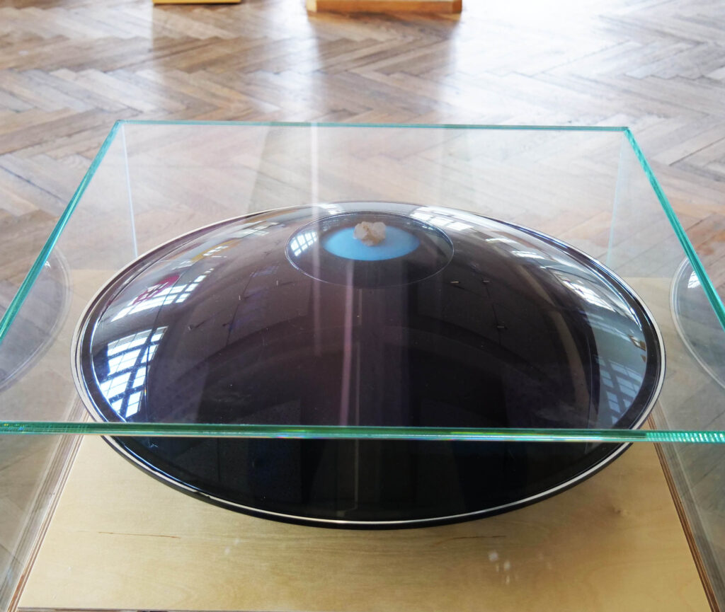
The “Mirage” exhibit shows an interesting optical illusion: a crystal lies in front of an observer as if on a platter. But if you reach for it, you simply — reach into the void. How is that possible? In the following text we will go into a little more detail about the mathematical background behind this illusion.

The exhibit uses two parabolic mirrors to create the strange effect. Such mirrors are also used, for example, in reflecting telescopes and in satellite communication.

Figure 1: The “Mirage” exhibit

And now … the mathematics:

What is a parabolic mirror and why is it so useful? To understand this, we first need to take a closer look at the parabola: The standard parabola, familiar from school lessons, is described by the equation y(x) = x^2. Let us now examine the properties of this curve in more detail. Trap for this purpose a light beam \mathbf{s}_x (x\in\mathbb R) from above; this can be described by the equation

    \[\mathbf{s}_x(t)=\begin{pmatrix} x\\ -t\end{pmatrix}=\begin{pmatrix} x\\ 0\end{pmatrix}-t\mathbf{e}_2.\]

Here t\in\mathbb R is a real parameter. At the point A=(x,x^2) this ray \mathbf{s}_x is now reflected. At this point the tangent has the normalised direction vector \mathbf{t}=\frac{1}{\sqrt{1+4x^2}}(1,2x). Thus the normal vector is equal to \mathbf{n}=\frac{1}{\sqrt{1+4x^2}}(-2x,1). We thus obtain for the direction vector of the outgoing beam \mathbf{s}_x'

    \[v=-\mathbf{e}_2+2\langle\mathbf{e}_2,\mathbf{n}\rangle\mathbf{n}=\frac{1}{1+4x^2}\begin{pmatrix} -4x\\ 1-4x^2\end{pmatrix}.\]

Here \langle\mathbf{u},\mathbf{v}\rangle is the scalar product of the vectors \mathbf{u} and \mathbf{v}. This makes the failing beam \mathbf{s}_x' given by the equation

    \[\mathbf{s}_x'(t)=\begin{pmatrix} x\\ x^2\end{pmatrix}+\frac{t}{1+4x^2}\begin{pmatrix} -4x\\ 1-4x^2\end{pmatrix}.\]

If we now set the x-coordinate to zero in this equation, we get t_0=\frac{1+4x^2}{4}. This gives

    \[F=\mathbf{s}_x'(t_0)=\begin{pmatrix} 0\\ x^2+\frac{1}{1+4x^2}\cdot\frac{1+4x^2}{4}(1-4x^2)\end{pmatrix}=\begin{pmatrix} 0\\ 1/4\end{pmatrix}.\]

All rays \mathbf{s}_x (x\in\mathbb R) incident from above are thus reflected in such a way that the corresponding outgoing ray \mathbf{s}_x' passes through the focal point F. In addition, we can still calculate the length of the route \overline{AF}:

    \[\lvert\overline{AF}\rvert=\left\lvert\begin{pmatrix} x\\ x^2\end{pmatrix}-\begin{pmatrix} 0\\ 1/4\end{pmatrix}\right\rvert=\sqrt{x^2+(x^2-1/4)^2}=\sqrt{x^4+1/2x^2+1/16}=x^2+1/4.\]

This distance therefore has exactly the same length as the distance from the point A to the horizontal y=-1/4 (the so-called directrix of the given parabola).

Functionality of the exhibit

The “Mirage” exhibit makes use of the above two properties of the parabola. To do this, one first rotates the standard parabola around the z axis and thus obtains the equation

    \[z=z(x,y)=x^2+y^2\]

of a so-called paraboloid of rotation P. This is also used for reflecting telescopes. So what is the idea behind the exhibit? We will describe this below. The principle behind this can also be used to transmit other waves (e.g. sound waves):

We take two parabolic mirrors P_1 and P_2. Let us say that the mirror P_1 is identical to the standard rotational paraboloid P. The mirror P_2 is now opposite the mirror P_1 at a certain distance d\gt 0. It is thus described by the equation z=z(x,y)=d-(x^2+y^2). If one were to continue the two parabolic mirrors P_1 and P_2 arbitrarily far (i.e. for all x,y\in\mathbb R) they intersect in the circle K given by the parametrisation

    \[\mathbf{x}(\varphi)=\begin{pmatrix} R_0\cos(\varphi)\\ R_0\sin(\varphi)\\ d/2\end{pmatrix}\]

for an angle \varphi\in[0,2\pi) with R_0=\sqrt{d/2}. For real purposes, however, we only need to continue the two mirrors up to a certain radius R\leq R_0 (i.e. for x^2+y^2\leq R^2).

Let F_1 and F_2 be the respective foci of P_1 and P_2. Then according to the above consideration

    \[F_1=\begin{pmatrix} 0\\ 0\\ 1/4\end{pmatrix}\]

and

    \[F_2=\begin{pmatrix} 0\\ 0\\ d-1/4\end{pmatrix}\]

holds. We now assume a beam that starts at the focal point F_1. Let us say that this is given by the equation

    \[\mathbf{s}(t)=\begin{pmatrix} 0\\ 0\\ 1/4\end{pmatrix}+t\begin{pmatrix} \cos(\varphi)\\ \sin(\varphi)\\ a\end{pmatrix}.\]

Here the parameter a measures the rise of the beam \mathbf{s}. In order for this to hit the mirror P_1, we need a relatively small slope of a\leq\frac{R^2-1/4}{R}. If the ray \mathbf{s} is now reflected at P_1, the outgoing ray then runs — according to the above considerations — parallel to the z-axis at a distance \leq R. This ray reflected at P_1 is then reflected again by P_2, so that the outgoing ray then passes (again as above) exactly through the focal point F_2. By the same reasoning, a ray \mathbf{s}' that starts in F_2 — if its slope a' is large enough (namely a'\geq-\frac{R^2-1/4}{R}) — will also arrive in F_1 after two reflections.

For applications, it is still important to know how long the distance covered by the above ray \mathbf{s} is on its way from F_1 to F_2. Let us assume that this is reflected at points Q_1 and Q_2 (the straight line Q_1Q_2 is therefore parallel to the z axis). Let r be the distance from Q_1 (and thus Q_2) to the z-axis. Then, as explained above:

    \[\lvert\overline{F_1Q_1}\rvert=r^2+1/4=\lvert\overline{F_2Q_2}\rvert.\]

So if we calculate the total distance travelled by the ray \mathbf{s} starting in F_1 from F_1 to F_2, we get:

    \[\lvert\overline{F_1Q_1}\rvert+\lvert\overline{Q_1Q_2}\rvert+\lvert\overline{F_2Q_2}\rvert=(r^2+1/4)+(d-2r^2)+(r^2+1/4)=d+1/2.\]

This distance is therefore independent of r.

So what are the applications of this construction? For example, this is a good way to transmit sound waves (or other waves) over a long distance d: To do this, place the sound source at the point F_1. The sound waves emitted by this source are now reflected at the parabolic mirrors P_1 and P_2 in the way we have just derived. Thus, after a certain time, which the sound needs to cover the distance from F_1 via the reflection points Q_1 and Q_2 to F_2, they concentrate again in the focal point F_2. But this time is proportional to the distance \lvert\overline{F_1Q_1}\rvert+\lvert\overline{Q_1Q_2}\rvert+\lvert\overline{F_2Q_2}\rvert, which — as derived above — has the constant length d+1/2 (independent of the outgoing beam). This means that there is also no distortion: The transmitted audio signal arrives at point F_2 from all directions at the same time. This mode of operation is exploited, for example, in satellite dishes.

The “Mirage” exhibit also uses this trick — but differently from radio wave transmission. While in this case the distance d between the two mirrors is particularly large, in our exhibit it is particularly small: let us set d=1/4 (i.e. exactly to the focal length). This time we do not place our “source” in the focal point F_1, but in F_2=(0,0,0). In a similar way we let the mirrors touch  each other , i.e. R=R_0=\frac{1}{2\sqrt{2}}. If a beam

    \[\mathbf{s}(t)=\begin{pmatrix} 0\\ 0\end{pmatrix}+t\begin{pmatrix} \cos(\varphi)\\ \sin(\varphi)\\ a\end{pmatrix}\]

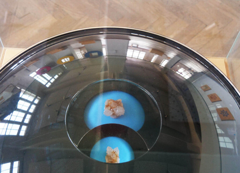
from F_2 and if the slope a\geq-\frac{R^2-1/4}{R}=\frac{1}{2\sqrt{2}} is large enough, \mathbf{s} is first reflected at P_2 and then at P_1 and finally “ends” in F_1=(0,0,1/4). Regardless of the rise and direction, the same distance of 3/4 is always covered. Thus, if one cuts out a small circular hole around F_1 in P_2, an object (in the exhibit: a crystal) that is actually located at the origin F_2=(0,0,0) suddenly appears to the observer as if it were located at the point F_1=(0,0,1/4) above it. This simple trick is used in the exhibit.

At this point it should be noted that if the crystal is mirrored twice, the orientation is also reversed twice, so that the crystal does not appear mirror-inverted either.

If you want to see another nice explanatory video on the above topics, have a look at the video [1]a, by YouTuber Mathologer.a,

Figure 2: Actual image and reflection of the crystal

Literature

[1] https://www.youtube.com/watch?v=0UapiTAxMXE

[2] https://de.wikipedia.org/wiki/Parabel_(Mathematik)

[3] https://de.wikipedia.org/wiki/Paraboloid

[4] https://de.wikipedia.org/wiki/Parabolantenne

Opening Hours and Ticket Prices

Tuesday – Friday: 9 am – 5 pm
Saturday, Sunday and holidays: 10 am – 6 pm

Entry: 5 Euro / discount. 4 Euro

Special prices apply for groups and families, for guided tours or for photo and video permission.

  • Legal Notes
  • Data protection
  • Accessibility
© 2022

Adress

Erlebnisland Mathematik
Technische Sammlungen Dresden
Junghansstraße 1-3
01277 Dresden

Visitor Service

0351 – 488 7272 | service@museen-dresden.de